Network Topology
How network structure affects the usefulness of a ferry system

Network topology is concerned with the arrangement of the main elements of a network. In the case of a public transport network, that means terminals and intermediate stops and the line segments that connect them. In the language of topology, terminals and intermediate stops correspond with vertices or nodes and line segments between stops are edges or arcs.
The topological shape of a network affects how passengers find their way between stops. Can the journey be made at all? Can transfers be made between lines? The shape also has a significant impact on operational management. Is there a single operational hub to facilitate crew and vessel changes and vessel maintenance or are there multiple hubs? Having multiple hubs can make a system more complicated to manage and reduce flexibility in the assignment of vessels and crews to sailings.
Vukan Vuchic (2005) describes the topology of metro trains. He makes a distinction between stations which are terminals – stations located at either end of a line; regular stations which are intermediate stops on one line only; and transfer stations, which are intermediate stops that connect with more than one line and allow passengers to transfer between lines.
The station sub-elements described by Vuchic are also applicable to stops in a ferry network. Three types of ferry stop are shown in a hypothetical ferry network in Figure 1.
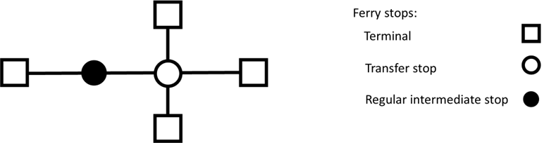
Figure 1: Graph representation of ferry stops in a hypothetical network
The ferry network in Figure 1 has two intersecting lines, four terminals, one regular intermediate stop and one transfer stop. Recovery time (additional time allocated in case of a delay) and an allowance for crew changes and other operational tasks are all scheduled at terminals, because it is inconvenient for passengers if their journeys are held up for these purposes at an intermediate stop.
Where transfer stops exist, there is the potential to substantially increase the number of connections between origin-destination pairs in the network. But a stop does not become a transfer stop just by being located on more than one line. To qualify as a transfer stop, convenient transfer wait times must be scheduled in all directions. This is achieved either by all the intersecting lines having a high frequency service or by synchronising arrival and departure times at the transfer stop.
Different topological shapes affect the way a network operates for both the operator and passengers, but there is not one “perfect” shape. The efficacy of a shape depends on local conditions. The table in Figure 2 presents four topological shapes with examples of ferry systems which incorporate them.
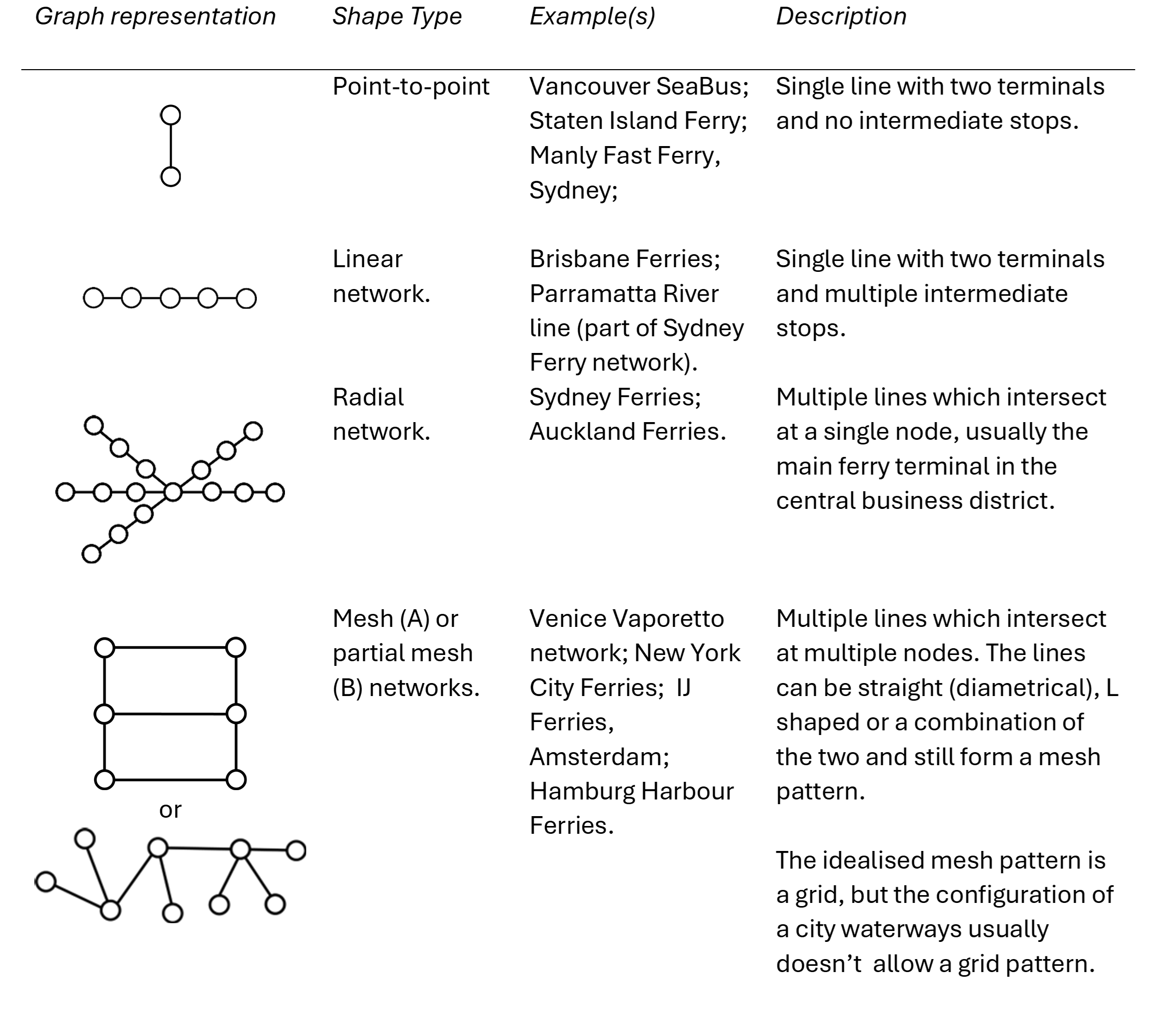
Figure 2: Four Ferry Network Topological Shapes
Other topologies are possible. A tree topology is one where either (A) a trunk line has feeders branching off it, or (B) two lines form a single trunk which separate into two branches. Both versions are shown in Figure 3 (adapted from Musso and Vuchic (1988)). The branches in Version A could be bus feeder lines.

Figure 3: Tree shape topology: (A) trunk line with branches; (B) two lines forming single trunk
Some ferry systems include a mixture of topological shapes. For example, the Sydney Ferries network incorporates three shapes which operate semi-autonomously – a radial network (inner harbour); a point-to-point line (outer harbour) and a river linear network (Parramatta River).
Point-to-Point Lines
Some of the most successful and best-known ferry systems are point to point lines. The point-to-point line makes a direct connection between two strategic locations on either side of a body of water where it is not practical or economic to build land transport via a bridge or tunnel. Point to point lines work best if they integrate well with other transport modes at both terminals.
An advantage of a point-to-point line is that the system is self-contained and independent. Vessels running on the line are not assigned elsewhere. This makes it easier to customise the design of vessels and wharf infrastructure. It also means operations are not affected by incidents on another line.
As a link in the city’s overall public transport system, the service is normally expected to operate to a memory or clockface timetable. It is often mandated in the transport authority’s planning guidelines. This can only be done efficiently if the cycle time (return trip time including turnarounds) is an integer multiple of the headway, otherwise vessels lie idle between sailings. The time and distance chart in Figure 4 provides an example of a ferry service with a 60 minute cycle.
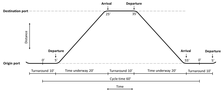
Figure 4: Time and distance chart representation of point-to-point ferry service on a 60 minute cycle
The Vancouver SeaBus, the Staten Island Ferry and Sydney’s Manly Fast Ferry all offer a memory timetable service and make efficient utilisation of vessels, as shown in Figure 5. In each case, the cycle time is an integer multiple of the headway. Note also that the number of operating vessels required for the system can be calculated by simply dividing the cycle time by the headway. The shorter peak turnaround of the Manly Fast Ferry is achievable because passenger exchange in the commuter peaks is usually uni-directional and faster.

Figure 5: Operational characteristics of a sample of point-to-point line schedules
Linear River Networks
A linear river network is a single line with a terminal at each end and multiple intermediate stops. Like point-to-point lines, it is also necessary for the cycle time to be an integer multiple of the headway to make efficient utilisation of vessels.
A river line may terminate at one end in the central business district (as it does in Sydney) or the CBD could be an intermediate stop around the middle of the line (as in the case of Brisbane) with the terminals on opposite sides of the city. The Brisbane Ferries network is an example of a pendulum or “through” line. A pendulum line can be viewed as two lines which are joined together in the centre of the city, but do not require passengers to change lines if their destination is a stop on the opposite side of town from where their trip originated.
Radial Networks
Radial networks have multiple lines which converge on a single hub, usually in the city’s central business district. It is a common design for traditional public transport networks where the objective is to funnel passengers from suburban areas into a city centre, mainly for the purpose of getting to and from work. The gradual decentralisation of work patterns in many cities makes this model less relevant to modern travel needs. Places of work now tend to be more widely distributed across a city. In any case, good quality public transport ought to be designed for all travel purposes, not just the commute to and from work.
While a radial pattern technically provides connections between all lines in a network – all lines intersect at the same hub - the length of the journey with a transfer may be inconveniently circuitous and long, unless the lines in question originate from opposite sides of the city, in which case the trip may be more direct.
From an operational perspective, a radial network has some advantages. There is a single operational hub which acts as a supply point for vessels and crew, making it possible to switch vessels between lines (“inter-lining”), to execute crew changes efficiently and perform minor maintenance tasks. Centralising resources at a single node increases the system’s efficiency. The capacity to inter-line vessels enables the operator to “hook” a vessel’s trips between different lines.
Mesh Networks
A mesh network resembles what transport planners often consider to be the ideal form for public transport – a grid. The metro systems of Paris and Tokyo are good examples. Coverage of an urban area by vertical and horizontal lines with connecting nodes at every point where the lines intersect is the most efficient way of bridging the largest number of origin-destination pairs. It also offers greater resilience than other network forms because there are more alternative paths to connect the same origin-destination pair. Geography is a barrier to building a comprehensive grid network for ferries, but a simple mesh ferry network, as shown in the graph in Figure 6, is possible.
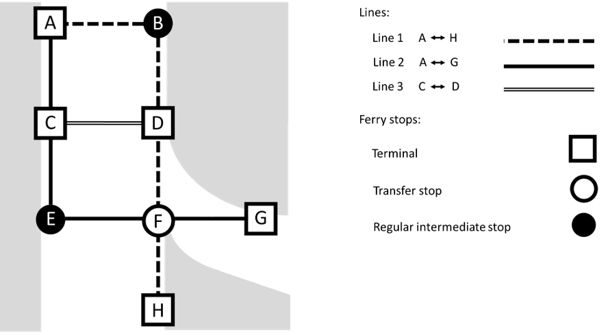
Figure 6: A graph representation of a hypothetical ferry network with mesh topology
This network has 3 lines and 8 stops. The mesh pattern is formed by a combination of L shaped lines (Lines 1 and 2) and a straight line (Line 3). In common with most transit networks, the graph is undirected, so passengers can travel in either direction on the same line segment. In this graph, every pair of stops is connected, either on the same line or by making one transfer between lines. For example, a passenger starting at Stop E on Line 2 can travel to Stop H by transferring at Stop F to Line 1.
Unlike a radial network, a mesh network does not have a single node which acts as an operational hub for vessels and crews. In the example in Figure 3.4, Stop A could be a hub for Lines 2 and 3, but Line 3 would need to use either Stop C or D as a hub. A ferry operator may consider this to be an unacceptable inefficiency as it complicates the task of assigning crews to vessels and reduces flexibility in the assignment of vessels to lines.
In practice, ferry networks with mesh properties are more likely to be partial mesh networks, which have several nodes for connecting lines but not with as effective coverage as a true grid because of geographical constraints. One example is Hamburg’s harbour ferries (network map at Figure 7). This network comprises a combination of point-to-point and linear lines with connections at 6 nodes. Each vessel is assigned to a single line. Where possible, there are well timed connections at nodes.
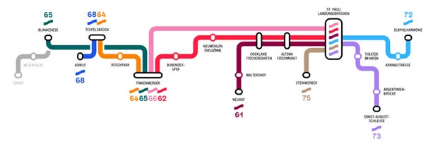
Figure 7: Hadag Hamburg Ferry Network Map
Tree networks
The most common application of a tree topology in ferry systems is one where a ferry route forms a trunk line with feeder bus line branches. This is a hierarchical structure – the smaller capacity bus lines are designed to support the ferry trunk line, which has a significantly larger capacity. Although the Sydney Ferries system was earlier described as a radial network, many of the individual ferry lines have a tree-like structure. One example is the F6 Mosman Bay line, shown in Figure 8, where bus lines connect with two intermediate stops and the terminal at Mosman Bay.
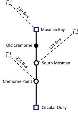
Figure 8: Mosman Bay ferry line with connecting bus lines
Conclusion
There is not one topological shape that is best suited for urban transit ferries. They each have strengths and weaknesses and the decision to choose one or the other (or a combination of shapes) must be based on local geography, operational requirements and how it integrates with other modes in the overall public transport network. But to do ferry planning well, it is important to have a good understanding of how topological structure affects passengers and operational management.
References
Levinson, David M and Sarkar, Somwrita (2025) A Web of Nets: How Everything is a Network
Musso, A. and Vuchic, V. R. (1988) Characteristics of metro networks and methodology for their evaluation, Transportation Research Record, 1162, pp. 22–33.
Vuchic, V. R. (2005) Urban Transit: Operations, Planning, and Economics(Hoboken, NJ: Wiley).
A lot of the tree bus-ferry networks in Sydney were actually formed in conjunction with the city's former tram system! Indeed routes 225 and 230, mentioned as feeders of the F6, were both once branches of the North Sydney Tramway System until well into the 50s! Most harbour wharves were, in fact, serviced by trams until the middle of the 20th century.